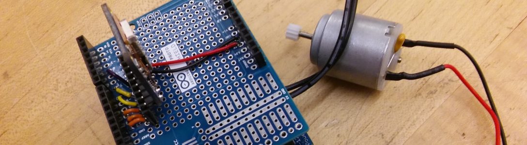
At first, I didn’t have much difficulty building the circuit and coding. I made the LEDs light up in response to the LDR on my first try, then I (incorrectly) drew the schematic scheme. Later, when I tried to replicate what I had drawn in my notebook, it did not work, then I realized that I was just lucky. The problem I had was I didn’t really understand how the circuit works, (for example, why put the wire connected to GND in a particular place, why connecting the LEDs and the LDR to different GNDs). Therefore, I tried connecting the LDR and LEDs to the same GND, changing the position of the wire connected to GND, and consulting the Sparkfun guidebook. After a few trials, I understood how it works. Then, I tested my new schematic diagram a few more times and it worked everytime. One thing that I still cannot figure out is that one time I tried making the LEDs blink in sequence, but 2 of the 3 LEDs blinked at the same time.
Schematic Diagram: 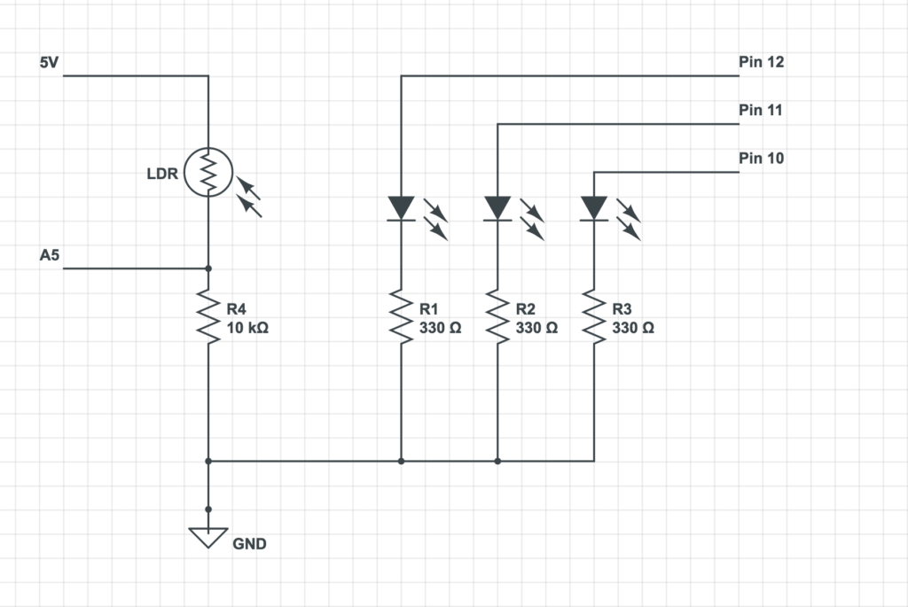
Code:
void setup() {
// initialize serial communication at 9600 bits per second:
Serial.begin(9600);
pinMode(11, OUTPUT);
pinMode(12, OUTPUT);
pinMode(10, OUTPUT);
}
void loop() {
int sensorValue = analogRead(A5);
Serial.println(sensorValue);
delay(1);
if (sensorValue > 800) {digitalWrite(12, HIGH);}
else {digitalWrite(12, LOW);}
if (sensorValue < 600) {digitalWrite(8, HIGH);}
else {digitalWrite(10, LOW);}
if ((sensorValue < 800) && (sensorValue > 600))
{
digitalWrite(12, LOW);
digitalWrite(10, LOW);
digitalWrite(11, HIGH);
}
else {digitalWrite(11, LOW);}
}
Video:
In the process I broke an LED and a resistor 🙂